Post layout in fixed tilt solar arrays and solar tracking systems
Whether the support structure on a solar site is fixed or moving affects post layout planning. The installation team must understand the system the post connects to, as well as the point list.
A common assembly plane for fixed tilt tables
In fixed tilt systems, posts support the panel table geometry defined by the design. Assess front and rear support elevations, connection hole orientation and post spacing together. The drawing must state the reference used to build the superstructure even where the ground surface changes.
Post tops appearing at the same height above the ground does not mean the entire row is correct. Checks must use finished ground levels and project coordinates. The installation team should know in advance which deviations can be accommodated by adjustment allowances in structural connections.
Geometry required for movement in tracking systems
In a tracking system, the structure moves with the sun's position. The rotation axis, bearing points and drive components place additional requirements on the post arrangement. Include the manufacturer's assembly sequence and permitted adjustments in the site installation plan.
IEC 62817 addresses design qualification tests for solar tracker components and complete systems. It does not replace project specific foundation calculations or checking each post's site position. State the applicable standard edition and system documentation in the design file.
Source: IEC 62817 — Design qualification of solar trackers (opens in a new tab)
Prepare the post list by function
Do not assume every post in a tracker row is identical. Depending on the project, end, intermediate or drive area posts may differ in section, connection or length. Matching product codes to installation points before distributing materials helps reduce incorrect post use.
| Check | Fixed tilt system | Tracking system |
|---|---|---|
| Geometry | Table inclination and connection plane | Rotation axis and bearing alignment |
| steel post ID | According to position in the table | According to function in the row |
| Installation inspection | Compatibility of structural connections | Connection compatibility and movement clearances |
Coordinate pile driving with superstructure assembly
Reviewing measurements from the first installation group with the superstructure team establishes a common reference before repetitive work starts. If deviations are found, record which points need correction and how measurements will be repeated.
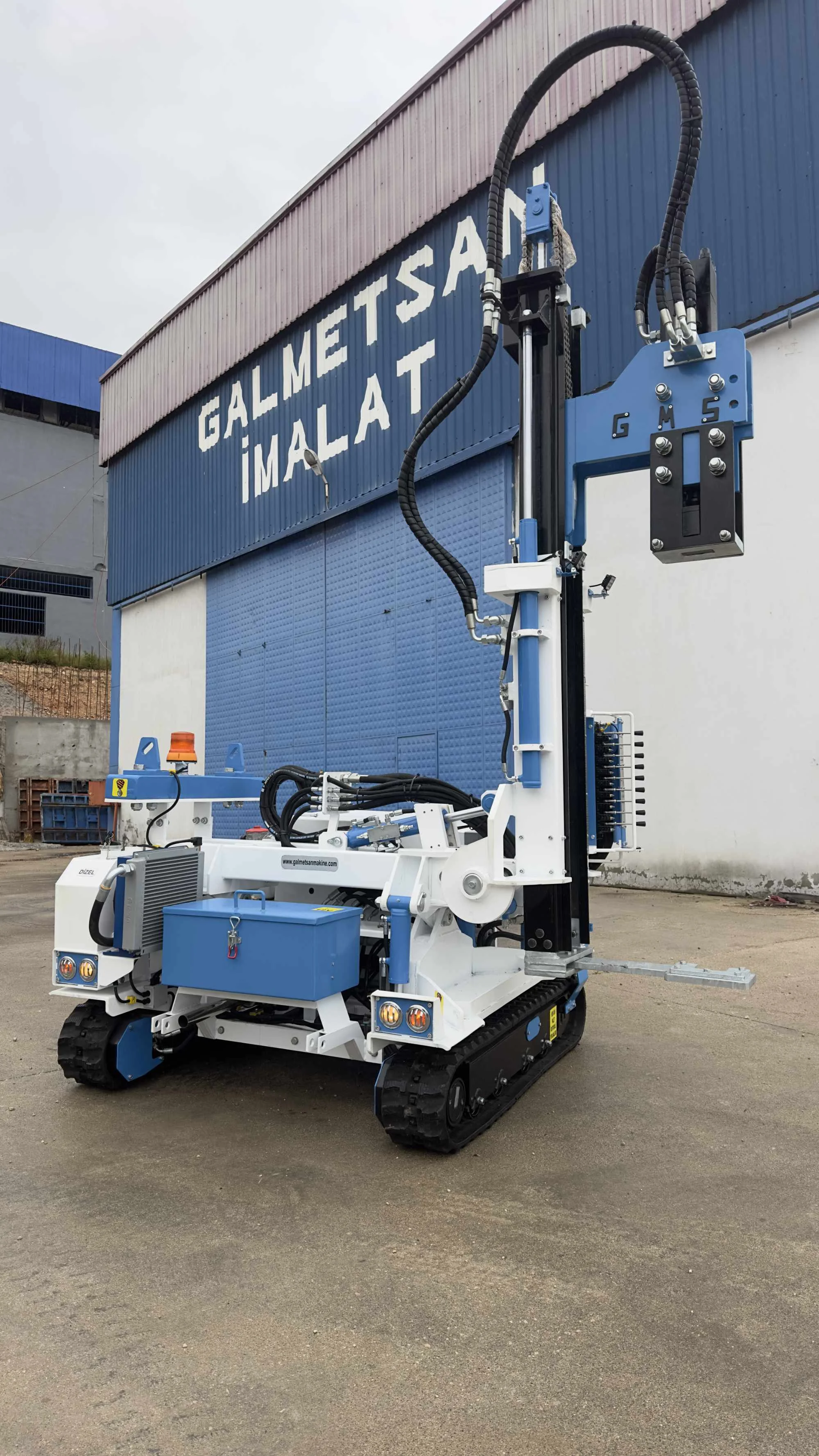
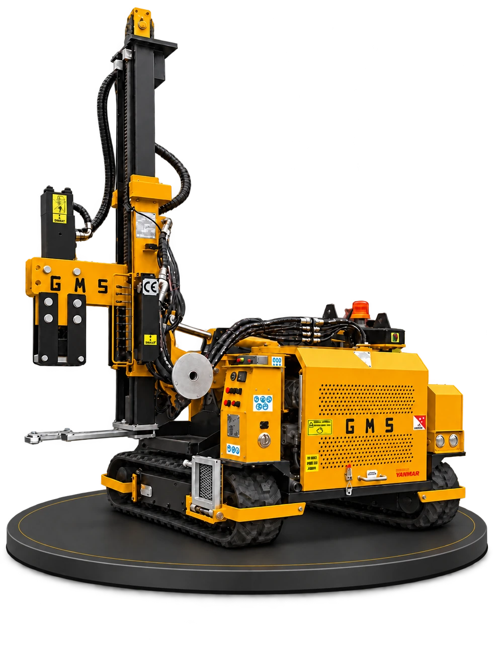
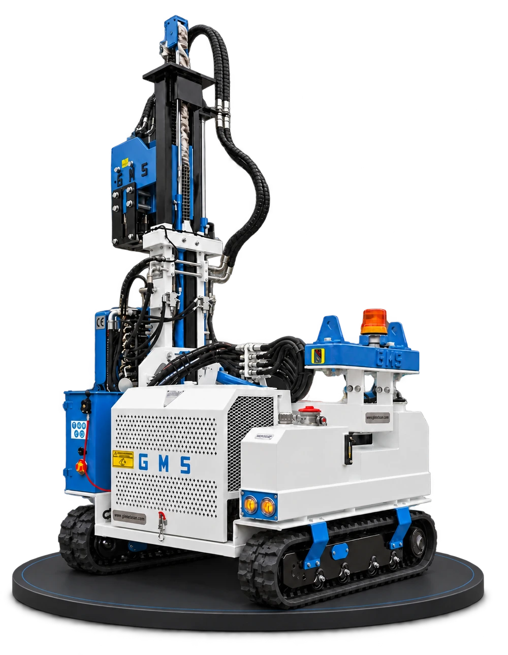
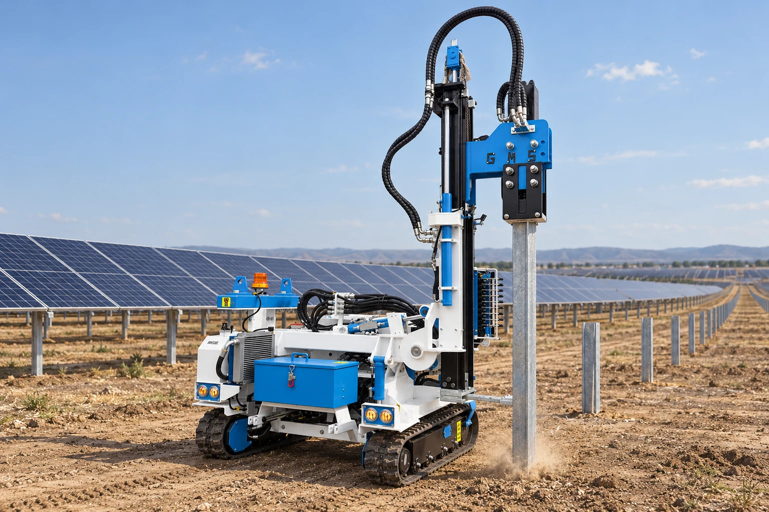
For work with GMS GES, clarify the profile drawing, post length and head compatibility with the manufacturer. Plan machine movement to preserve access to connections not yet installed. This keeps other teams' working areas open as the pile driving team advances.
- Use the system manufacturer's current layout drawing.
- Match steel post IDs to site points.
- Share initial group measurements with the superstructure team.
- Obtain a technical assessment for deviations beyond adjustment allowances.
Posts for fixed and moving systems follow different layout requirements. Correct installation begins by translating structural geometry into the pile driving plan.
Sources and further reading
The scope of the standards is summarized here. In practice, the project specification, applicable editions of the standards and the assessment of the responsible engineering team take precedence.